![]()
![]()
![]()
![]()
![]()
![]()
![]()
|
The Spaceships of Ezekiel |
|---|
|
The Spacecraft - Part E |
|
|
|
|
|
|
|
|
|
|
|---|
|
Keywords: UFO, unidentified flying objects, Bible, flying saucers, prophecy, Paleo-SETI, ancient astronauts, Erich von Däniken, Josef F. Blumrich, Zecharia Sitchin, Ezekiel, biblical prophecy, spacecraft, spaceship, NASA, Roswell, aircraft, propellant, extraterrestrial hypothesis, Jacques Vallee, interdimensional hypothesis, Project Blue Book, Condon Report, ancient history, Jesus, Judaism, Christianity, Middle East, end times, engines, rockets, helicopters, space travel, aliens, abductions, alien abductions, crop circles, extraterrestrials, astronomy, economics, biology, Venus, Mars, Jupiter, Saturn, Space Shuttle, Apollo, stars, planets, solar system, scriptures, design, fuel tank, aerodynamics, fuels, hydrogen, oxygen, wheels |
|
|
|
|
|||||||||
|
|
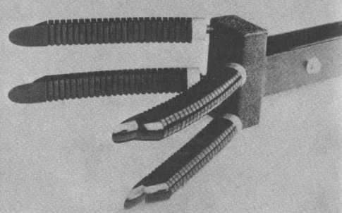
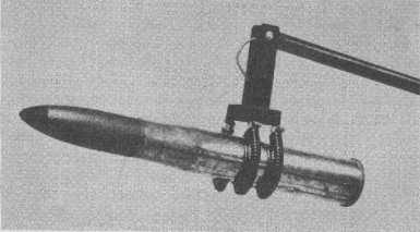
THE SPACECRAFT The control rockets are used to perform small attitude corrections or course corrections in flight. The principle of their arrangement is shown in Fig. 7. [p.34] Figure 7 Mechanical arm and control rockets Usually the control rockets are fired only briefly and they produce relatively small amounts of thrust. They are, in a way, the equivalent of the rudder of an aircraft or a ship. Depending on how many such small rockets are fired in short blasts, the vehicle can be rotated, tilted, or translated. An example from our own times: Anyone who has had a chance to watch the U.S. Apollo program on film or television will certainly recall the flashing of the control rockets as the module, coming up from the moon, was approaching the command capsule. Two to four mechanical arms, operated by remote control, are fastened on the outside immediately below the rotor; when not in operation they hang downward. Each of these arms consists of a forearm and an upper arm, has an elbow, a wrist, and a hand. To extend the reach, the forearm and upper arm may be designed as telescoping members, which would give the mechanism roughly the appearance shown in Fig. 7. Near the shoulder and the wrist television "eyes" are probably installed to observe position and movements of the hand. Remote operation and control of the mechanical arms are performed from the command capsule. Even today, arms of this or similar types are already well-established technical products. Large-size versions of such arms are being investigated under the U.S. Shuttle Program. Figs. 8a and 8b show the shape of such a "hand." Tread such as that used in heavy tractor tires is installed on the inner part of the hand to improve grip.
We see here an excellent example of the similarity between technically highly developed structures and "natural" shapes serving the same purpose. Each landing leg consists of a simple straight shock absorber, which works in a telescopic fashion under load, and of a round disklike foot. The disk's purpose is to distribute the ground pressure over a surface large enough to prevent it from sinking into the ground. The underside of the foot usually has a convex shape to permit sliding, which may become necessary, for example, in case of a crosswind landing. It may be of interest to mention here that it was the accurate description of these feet that motivated me to investigate Ezekiel's report more closely. Ezekiel says:
Since I was involved myself in the design and testing of such "feet" years ago, Ezekiel's words made immediate sense to me. The wheels allow rolling movement in any direction, without need for turning. This complex requirement can be met in a surprisingly simple manner. Figure 9 The principle of achieving wheel movement in any direction Let us imagine the inner tube of an automobile tire (see the schematic movements in Fig. 9). It rolls, as we know, in the direction of arrow 1. If, however, we twist that tube in itselfas indicated by arrows 2then it will move along arrow 3, at a right angle to its customary rolling direction. An appropriate combination of the two directions of rotation will let the inner tube roll along any desired direction. With that, the problem is solved in principle. The simplest design resulting from the application of that principle is shown in Fig. 10. We see the "tire" divided into a number of barrel-shaped segments that are connected to the hub of the wheel by means of spokes. Both directions of rolling are achieved by the rotation of the wheel around its hub on the one hand and by the rotation of the segments around their own axes on the other. Ezekiel has devoted special attention to the description of the wheels. The texts have often been misinterpreted. For this reason the technical Appendix to this book includes a detailed investigation of the wheel. At this point, therefore, it only remains for us to investigate the meaning of the repeatedly mentioned "eyes." Figure 10 Structural layout of a wheel Fig. 10 shows the barrel-shaped segments as having a smooth surface, which would result in a minimum of friction between wheel and ground. To increase friction, or sliding resistance, it is necessary to provide a profile. Resistance to slipping, however, is needed in two directions: in the plane of the wheel and perpendicular to the plane. Tread such as is used in heavy tractor tires or caterpillars would not be useful, because it would transmit the driving force only in the plane of the wheel. The simplest and most efficient solution is short protrusions thatsimilarly to the so-called sheepsfoot rollers used in road constructionare distributed over the surface of the segments. "Sheepsfoot", incidentally, is yet another example of how even now we still resort to figurative talk in identifying a modern device. The short protrusions must be slightly conical-like the half-retracted eyes of a snail. To facilitate penetration into the ground they may be hollow: They would then have dark openings on their free ends. Seen from some distance, such dark openings can be legitimately compared to "eyes." It should be further mentioned that the solution and design I developed for the wheel were found to meet patent requirements and on 5 February 1974 U.S. Patent No. 3,789,947 was issued for an Omnidirectional Wheel. With regard to the complete helicopter units another consideration is necessary. . . . [p.39] |
|
| |
www.SpaceshipsOfEzekiel.com