|
The Spaceships of Ezekiel |
|---|
|
Appendix - Part G |
|
|
|
|
Keywords: UFO, unidentified flying objects, Bible, flying saucers, prophecy, Paleo-SETI, ancient astronauts, Erich von Däniken, Josef F. Blumrich, Zecharia Sitchin, Ezekiel, biblical prophecy, spacecraft, spaceship, NASA, Roswell, aircraft, propellant, extraterrestrial hypothesis, Jacques Vallee, interdimensional hypothesis, Project Blue Book, Condon Report, ancient history, Jesus, Judaism, Christianity, Middle East, end times, engines, rockets, helicopters, space travel, aliens, abductions, alien abductions, crop circles, extraterrestrials, astronomy, economics, biology, Venus, Mars, Jupiter, Saturn, Space Shuttle, Apollo, stars, planets, solar system, scriptures, design, fuel tank, aerodynamics, fuels, hydrogen, oxygen, wheels |
|
|
|
|
|||
|
|
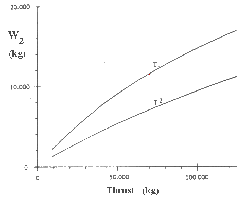
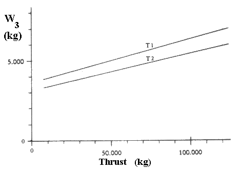
Go to Appendix Part: A B C D E F G H I J W1: Main Body. This figure includes the weight of the central main body, the propellant tank, and the helicopter support structure. As described earlier, it consists mostly of stiffened thin-walled shells. The outstanding exception is the compression ring located in the area of the largest diameter of the structure, which constitutes a substantial local weight concentration. [p.164] For our calculation it is necessary to express the weight of this group in terms of only one parameter—for which the maximum diameter is an obvious choice. We will therefore use a circular disk of a certain thickness for the weight determination. For a given level of development, thickness will be kept constant independent of diameter. The latter assumption neglects minor variations which are caused by a certain dependence of the structural thicknesses on the diameter. The thickness of the disk is the sum of the average wall thicknesses in vertical direction of the various structures, and constitutes therefore something like a "substitute wall thickness", which also includes all internal structures. Considering present-day aluminum properties, this substitute thickness is estimated at 15 millimeters (0.59 inch). A course calculation indicates that the weight of the large compression ring will amount to about 20-30 percent of the total weight, and the thickness of the disk is therefore increased to 20 millimeters (0.79 inch). The influence of a higher technology will be expressed by a reduction in thickness at the same specific gravity. The enormous progress made in the field of material sciences during recent years, and the prospects it indicates, allow the assumption of rather drastic reductions. The fact that buckling is less dependent on the ultimate strength than on the modulus of elasticity of a material is of only little consequence in a structure such as discussed here because its parts are mainly loaded in tension. The disk thickness will therefore be assumed to be 12 millimeters for T1, and 9 millimeters for T2. The following weight figures will thus be obtained: T2 W1 = 19.8D2 The diameter D of the main body depends on the propellant volume required for a certain total weight. We saw earlier that the ratio of tank volume and size of the main body can be kept constant and we found the expression V = 0.0963D3 We can determine the propellant volume V from the propellant weight 1.1 W9 and the specific gravity of liquid hydrogen, 70.8 kg/m3 (4.4 lb/cu ft). By introducing these values in the above weight figures, we can express diameter and weight of the main body in dependence of W0. W2: Main Power Plant. This consists of the reactor and the plug nozzle. In this case it is particularly difficult to arrive at a weight estimate because with regard to the reactor we are still at the beginning of a very promising development, and because, furthermore, there is only scant information available in the open literature on existing reactors. Fig. 20 shows the relationship between thrust and weight of the power plant for T1 and T2. W3: Radiation Shield. The expected values are shown in Fig. 21. W4: Helicopter Drive. The weight of power plants is usually expressed in terms of their performance. It is therefore necessary first to determine the power requirement of the four rotors. The weight to be lifted is W0.  Figure 20 Weights of the main power plant  Figure 21 Weights of radiation shield The performance required to lift that weight at a velocity v is (Reference 18):
[p.166] |
|
| |
www.SpaceshipsOfEzekiel.com