|
The Spaceships of Ezekiel |
|---|
|
Appendix - Part H |
|
|
|
|
Keywords: UFO, unidentified flying objects, Bible, flying saucers, prophecy, Paleo-SETI, ancient astronauts, Erich von Däniken, Josef F. Blumrich, Zecharia Sitchin, Ezekiel, biblical prophecy, spacecraft, spaceship, NASA, Roswell, aircraft, propellant, extraterrestrial hypothesis, Jacques Vallee, interdimensional hypothesis, Project Blue Book, Condon Report, ancient history, Jesus, Judaism, Christianity, Middle East, end times, engines, rockets, helicopters, space travel, aliens, abductions, alien abductions, crop circles, extraterrestrials, astronomy, economics, biology, Venus, Mars, Jupiter, Saturn, Space Shuttle, Apollo, stars, planets, solar system, scriptures, design, fuel tank, aerodynamics, fuels, hydrogen, oxygen, wheels |
|
|
|
|
|||
|
|
Go to Appendix Part: A B C D E F G H I J The performance required to lift that weight at a velocity v is (Reference 18): [p.166]  For the hover flight the formula is: 
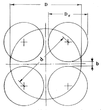
This is justified if we consider that we are here not calculating the dimensions of a hardware project but rather are attempting to establish approximate dimensions in order to check the feasibility of a vehicle. We will therefore assume a 20 percent performance increase and as a further precaution, a low degree of efficiency of 0.75. Under these conditions we obtain the following expression for the total power requirement of all four helicopters:  This formula shows us that the power requirement decreases with increasing rotor diameter Dr. The weight calculations are made for a broader range of rotor diameters; still, it is necessary to determine the maximum possible size of the rotors. The geometrical relationships and the largest possible rotor diameter resulting therefrom are shown in Fig. 22, where it is assumed that D = l.ld; b = 0.04Dr. Result: max Dr = 0.618D. With regard to the selection of the ratios indicated there, it should be noted that the edge distance of the helicopters is relatively large (D = 1.ld). That results in a maximum Dr that is smaller than what could be expected in an actual design. The resulting weights will therefore be conservative, that is, slightly on the high side.  Figure 22 Geometry of the helicopter arrangement Returning to the performance formula, we can begin the weight determination. In the technical description we have established a turbine as the characteristic element. With regard to its weight, such power plant can neither be compared to a stationary plant, nor can we use the turbines of our rocket engines, which are highly sophisticated because of their short service life, for that purpose. It was only natural, therefore, to derive the weight from aircraft turboengines. Reference 19 contains a long list of existing engines, from which dry weights as low as about 0.1 kg/hp (0.22 lb/hp) can be determined. In view of the general uncertainty concerning the actual character of the power plant, the value is only slightly reduced to 0.09 and 0.075 kg/hp (0.2 and 0.17 lb/hp) for T1 and T2, respectively. Due to the internal composition of such an engine these figures also include at least part of the generator weight. Both the number of the remaining elements for the transformation and transmission of energy, as well as the impossibility of defining them better, prevent us from estimating the weights of any other components. We bypass that problem by assuming that all other parts of the power plant weigh about 1.5 times the turbine weight. That brings the total weight up to 2.5 times the unit weights and we obtain:
W5: Rotor Weight. Current designs would be assessed at about 8-12 percent of the lift-off weight. We will maintain the lower one of these two figures in order to compensate for details that cannot be assessed, and we set for T1 and T2 W6: Landing Gear. Aircraft landing gears weigh about 6-8 percent of the landing weight. In comparison with the landing gears of current heavy aircraft, the landing legs used here are very simple lightweight structures, and their weight percentage is therefore considerably lower. The weight W6, however, must also include the weight of the wheels. The latter are not used for the landing but only later for a slow rolling on the ground; relatively low weights can therefore be expected for them too. It will be assumed, consequently, that the sum of the weights of both elements is safely covered by the lower of the current weight figures. Since, moreover, the main dimensions of both the footpad of the landing leg as well as the wheel depend on the load-carrying capability of the soil, which is independent of technological developments, we set for T1 and T2 W6 = 0.06W0 W7: Command Capsule. As we have seen, the capsule is relatively small and practically independent of the dimensions of the spacecraft. Its weight is estimated at 1500 kg. Since this is a very small percentage of the total spacecraft weight, the figure will be kept constant for all spacecraft sizes and for both levels of technology. [p.170] 3. Results |
|
| |
www.SpaceshipsOfEzekiel.com